Summary of the C919 Engine-Out Procedure
Today, instead of writing about components, I'll share my personal understanding of the engine-out procedure. My capabilities are limited, so errors are inevitable. This article focuses only on the general procedure and does not analyze every possible scenario in detail (e.g., fire, surge, low oil pressure, etc.).
Engine Failure at V1
1. Transition Logic
The logic for transitioning to CON (hereinafter referred to as MCT - Maximum Continuous Thrust):
- AP/FD multi-axis mode is no longer in TO/GA
- One engine fails
Based on this, during thrust transition logic, the system will briefly jump to CLB mode to bridge the transition to MCT thrust.
Although I don't know why COMAC designed it this way, we can take this opportunity to understand the conditions under which a normal takeoff switches from TO to CLB mode:
- After TO mode is engaged, above 800 ft AGL and reaching thrust reduction altitude (see Figure 2, reaching EO ACCEL point)
- (And FMS requests thrust reduction)
For detailed steps, refer to Figure 1. My drawing skills are limited, so please forgive me. For those undergoing type conversion training, this can serve as an introductory understanding of the procedure.
2. Analysis
Assume the EO ACC ALT (Engine-Out Acceleration Altitude) at the airport is 1500 ft. After VR and liftoff, maintain a pitch attitude of 12.5° and a target speed of V2 or the engine-out speed (but in any case, not exceeding V2 + 15). At 400 ft AGL, we may choose to start the QRH (Quick Reference Handbook) procedures. This is also Airbus' minimum requirement, as fire ECAM warnings only appear at 400 ft.
However, a golden rule remains: Aircraft control always comes first.
For example, at around 700 ft AGL, after stabilizing the aircraft, begin the QRH.
Why is there a step to disconnect the autothrottle (AT)?
Because of the cable control system, you need to manually reference the FMS N1 LIMIT page to select CON and identify the corresponding N1 setting. Then, using the EICAS N1 indication, manually adjust the Throttle Lever Angle (TLA) of the functioning engine.
Once you reach Vfto (the green dot speed), perform the after takeoff checklist, reconnect AT, and MCT is automatically restored.
- FMA:
AT ← MCT HDG/LNAV FLCH/ALT
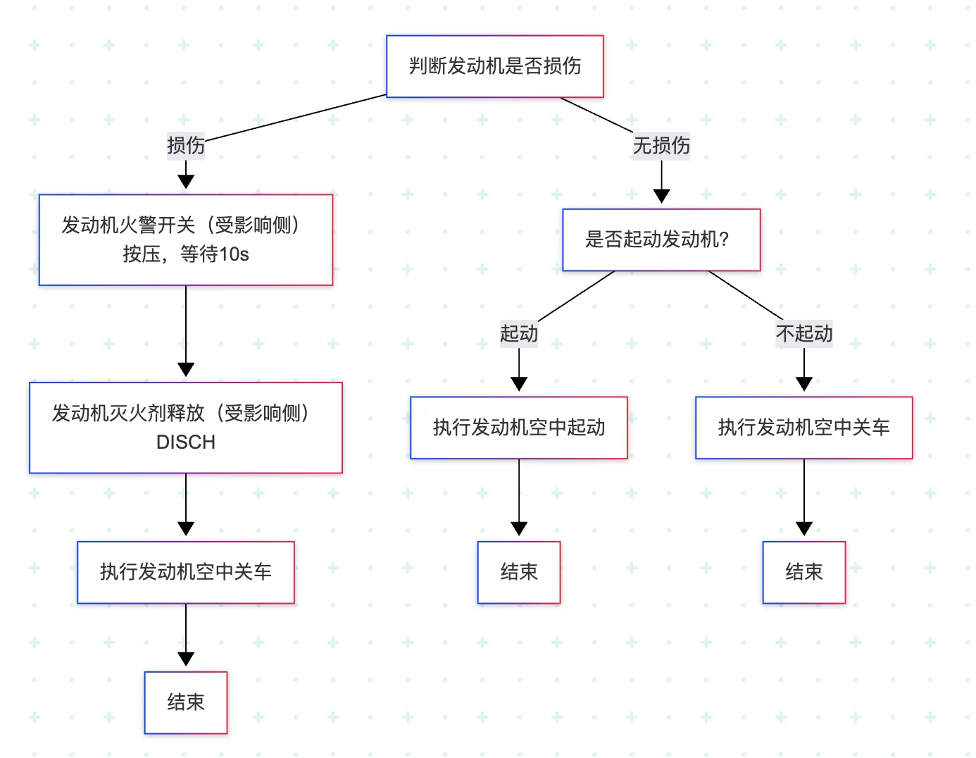
QRH Procedure:
Standard Steps:
- Disconnect AT
- Retard the affected engine to idle
- Cut off the fuel
Details:
See Figure 3
3. Notes
- There is no specific differentiation between FIRE, FAIL, LIMIT, surge, or stall. The same CAS (Crew Alerting System) information appears.
- When there is a FIRE, EICAS displays:
FIRE - When there is a Vibration issue, EICAS displays:
VIBEwith vibration value exceeding limits
Figure 1:
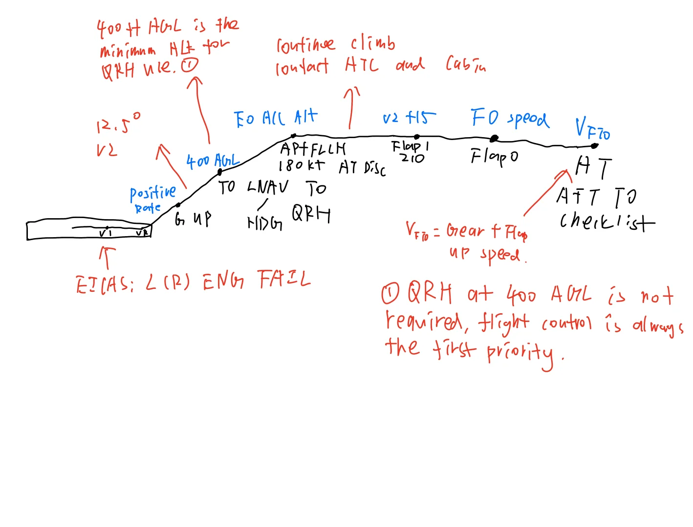
Figure 2:
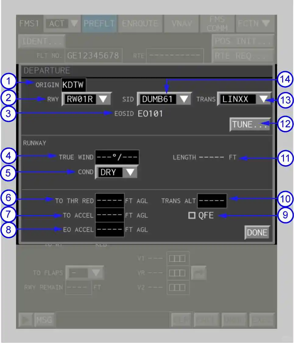
Figure 3: